
mining process flow diagram symbols cad manufacturer Grasping strong production capability, advanced research strength and excellent service, Shanghai mining process flow diagram symbols cad supplier create the value and bring values to all of customers.
 WhatsApp)
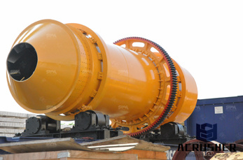
flowsheet equipment symbols mining process. Our Purpose And Belief. L&M Heavy Industry is committed to provide the global customers with the first-class products and superior service, striving to maximize and optimize the interests and values of the customers, and .
yEd is a powerful diagram editor that can be used to quickly and effectively generate high-quality drawings of diagrams.Create your diagrams manually or import your external data for analysis and auto-magically arrange even large data sets by just pressing a button.Features :yEd can be used to automatically lay out complex data sets.
This article will explain the procedure for creating Piping and Instrumentation Diagram (P&ID) or Piping flow diagram or process flow diagram using AutoCAD. Piping and instrumentation diagram (P&ID) sometimes called piping flow diagram or process flow diagram is a kind of schematic drawing, which shows the sequence of process equipments and instrumentation.
I've put together a list of pump symbols that you might encounter, mainly for identification purposes. Please do not request the blocks for these symbols, as I will not provide them. In the next few weeks I will put together a process for creating and adding your own symbols to AutoCAD P&ID's database. General Pump Symbols:
There's an extensive variety of process flowcharts and diagrams which are usually being used for giving everyone a clear understanding of some process, helping identifying non-value-added operations, facilitating teamwork and communication, keeping everyone on the same page, designing the flow charts and flowchart construction.
Process flow diagram – Wikipedia, the free encyclopedia. A process flow diagram . CAD packages, or flow chart software using a library of chemical engineering symbols. . Graphical Symbols For Process Flow Diagrams . »More detailed
Copper Mining & Extraction Process Flow Chart. Previous Next. View Larger Image. This flowchart made of machinery icons explains or expresses in simple but clear terms the step of the Copper Mining and Copper Extraction Process. Starting from either open-pit or underground mining and using a different relevant treatment method for oxide or ...
ConceptDraw is Professional business process mapping software for making process flow diagram, workflow diagram, general flowcharts and technical illustrations for business documents. It is includes rich examples, templates, process flowchart symbols. ConceptDraw flowchart maker allows you to easier create a process flowchart. Use a variety of drawing tools, smart connectors, flowchart symbols ...
symbols for drawing mineral processing flow sheets manufacturer in Shanghai, China. symbols for drawing mineral processing flow sheets is manufactured from Shanghai Xuanshi,It is the main mineral processing solutions.. XSM stone crushing machine project-symbols for drawing mineral processing flow sheets
Feb 25, 2018· What is Autocad p&id? how it is beneficial over conventional autocad software for making p&id diagram. ... AutoCAD Plant 3D: Process Flow Diagrams ...
This article will explain the procedure for creating Piping and Instrumentation Diagram (P&ID) or Piping flow diagram or process flow diagram using AutoCAD. Piping and instrumentation diagram (P&ID) sometimes called piping flow diagram or process flow diagram is a kind of schematic drawing, which shows the sequence of process equipments and instrumentation. P&ID is used for erection and ...
Jun 05, 2017· Besides modeling Piping Systems in 3d using Solidworks Routings, there is a need to generate Piping and Flow Diagram drawings with Ansi piping and instrumentation symbols schematically. Does Solidworks have the ability to create a P .
Symbols used in Process Flow Diagram (PFD) or Process Flow Scheme (PFS) Piping & Instrument Diagram (P&ID) or Process Flow Engineering Scheme (PEFS) Process & Instrument Diagram Visit Today -
Working with Process Flow Diagrams Chapte r 1: ... In AutoCAD MEP, a process flow diagram is also called a schematic diagram. You create process flow diagrams by using the schematic symbols and lines that model the components of a piping system. S a m p l e P C h a p t e r A u t o
Pneumatic Symbols Only when the design fails does it draw attention to itself; when it succeeds, it's invisible. John D. Berry All the symbols you need to design your pneumatic circuit in .dxf format. Scan through and easily download the one you need.

Recent Certification Topics. ISA Digital Badges and Certificates. Featured Whitepaper: Addressing the Workforce Demands of Modern Industry. ISA to develop a new certification program as part of a $23 million grant to fund degree programs and prepare workers for careers in "Mission Critical Operations"
Process Flow Diagram is a simplified sketch that uses symbols to identify instruments and vessels and to describe the primary flow path through a unit. It illustrates the general plant streams, major equipments and key control loops. They also provide detailed mass/energy balance data along with stream composition and physical properties.

Insert P&ID components from the icon menu. The P&ID symbol library in AutoCAD electrical includes equipment, tanks, nozzles, pumps, fittings, valves, actuators, logic functions, instrumentation, flow, and flow arrows. The P&ID symbol library consists of all the piping and instrumentation symbols. It is found at UsersPublicDocumentsAutodeskAcade {version}LibsPid.
Common Flow Diagram Cad Symbols For Quarry Equipment. diagram autocad zenith stone crusher - nutanschool. mining process flow diagram symbols cad; ... schematic symbol for crusherstone quarry in ... Chat with us. stone crusher plant layout cad drawing - Documents. 1. Get price
Five Basic Flowchart Symbols. Flowcharts are the ideal diagrams for visually representing business processes. For example, if you need to show the flow of a custom-order process through various departments within your organization, you can use a flowchart.
A schematic drawing is a two-dimensional (2D), not-to-scale flow diagram that shows the logic and operation of a building system. You draft a schematic or single-line diagram of your system to use as a basis for your complete design layout, or to create plumbing riser diagrams or details associated with your design. Generally, drafting a schematic diagram is one of the first steps in the ...
May 15, 2019· I've used Microsoft Visio quite a bit it is pretty quick and easy, but I don't think its cheap. It includes loads of templates and works like Word. otherwise, my company almost always just uses AutoCAD, we've developed a large collection of flowchart symbols.
PFD is Process Flow Diagram. P&ID is Process or piping & Instrument Diagram. PFS means Process Flow Scheme and PEFS means Process Engineering Flow Scheme. Here, I have tried to cover symbols that regularly used on the P&ID and PFD. There are other symbols also you can check the full list of the symbol by visiting this link. I advised you before ...
common flow diagram cad symbols for quarry equipment Flowchart Symbols Meaning Explained | Lucidchart If you get confused while drawing your flow chart, remember that most charts can be drawn with just a few common symbols, which are listed below.
WhatsApp)