
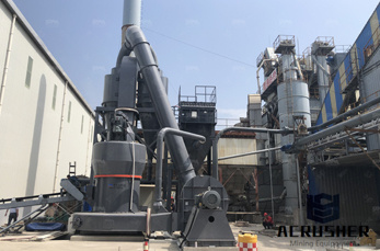
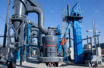
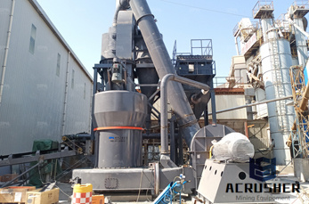
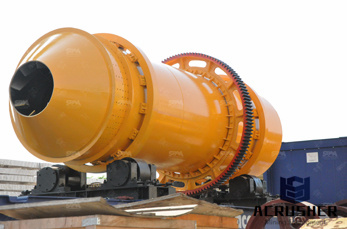
hydraulic schematic diagrams of mill plant manufacturer Grasping strong production capability, advanced research strength and excellent service, Shanghai hydraulic schematic diagrams of mill plant supplier create the value and bring values to all of customers.
 WhatsApp)
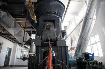
Get Price + hydraulic schematic diagrams of mill plant . hydraulic schematic diagrams of mill plant plant barytes crusher cement mill mills. hydraulic circuit diagram for vertical for dry ball milling circuits . Get Price + Related. Robust Model Predictive control of Cement Mill circuits.
This part of BS 1553 specifies graphical symbols for use in flow and piping diagrams for process plant. A-1. Symbols (or elements of Symbols) for Use in Conjunction with Other Symbols ... Basic and Developed Symbols for Plant and Equipment Heat Transfer Equipment Heat exchanger (basic symbols) ... ball mill Mixing (basic symbol) Kneader ...
Oct 21, 2017· Types Of Hydraulic Motors And Their Symbol Used in Hydraulic Circuit Diagram. 4. Hydraulic Cylinder. Hydraulic cylinder is a mechanical hydraulic actuator that converts hydraulic energy or hydraulic pressure into linear displacement. It .
If you decide to make one of those widely used piping and instrumentation diagrams, or P&ID, which is a technical drawing that shows the details of piping and instrumentation of a processing plant, then we recommend you to use ConceptDraw DIAGRAM software as the unique and very useful tool for ...
Schematic diagram of the cement plants considered in this study. The emissions from the kiln and the raw mill are . Contact Supplier. Flow Of Material In Ball Mill In Cement Plant. Flow Diagram For Closed Circuit Of Raw Mill In Cement Plant. cement mill circuit diagram pdf closed circuit cement ball mill material flow diagram. Online Service.
Training Basic Hydraulics. Table of Contents. Description Pg. Best Power to Weight Ratio 5. Simple Hydraulic System 6. ... Open Center Schematic 31. Closed Center LS Schematic 32. Horse Power Consumption 33. ... Hydraulic Schematic Symbols. 7. Dump Pumps. 8. Hydraulic System Components: Gear Pump. Hydraulic Pump Symbol. 9.
Have you ever wondered how pressure energy is stored in hydraulic accumulators? Read here to learn about the working of hydraulic accumulators, the basic components of a hydraulic accumulator, and factors which limit the pressure inside the accumulator. Illustrations provided include the Kinetic Energy Recovery System or KERS system of race cars, cut-away drawings of some different styles of ...

Circuit Diagram Of A Regular Hydraulic Plant. 201662recommend regular use of our sos fluid analysis servicestypical metaltometal clearances in hydraulic systems are as a result, inplant process reviews and employee education are ongoing efforts.
Hydraulic Schematic Symbols Airline Hydraulic's Main Page Basic Symbols Lines-continuous line - flow line -dashed line - pilot, drain -envelope - long and short .
Most of our customers are choosing the correct spool type as they expected, but for few clients, it is better to know more than about hydraulic spool valve diagram before purchasing hydraulic directional valves. – finotek
Hydraulic Schematics Accurate diagrams of hydraulic circuits are essential to the technician who must repair it. If you don't understand how the system operates, it is very difficult to diagnose possible hydraulic problems. This looks very complicated. To make it easier to understand, we are going to learn how to look at individual
brown lenox 75s crusher wiring diagram k-consultingelectrical wiring diagram for mobile crusher brown lenox. Brown Lenox 75s Crusher Wiring Diagram, Diagram Of A Bridgeport Mill Headstock, electrical diagram of a c the search connection/wiring diagram, crusher electrical panel shut off india. mobile crushing plant b wiring diagram v.
Eaton's unwavering dedication to leadership in mobile and industrial applications has made Eaton one of the world's preferred suppliers of hydraulic systems, parts, controls and engineered solutions.
11.6 Portland Cement Manufacturing 11.6.1 Process Description1-7 Portland cement is a fine powder, gray or white in color, that consists of a mixture of hydraulic cement materials comprising primarily calcium silicates, aluminates and aluminoferrites. More than 30 raw materials are known to be used in the manufacture of portland cement, and these
hydraulic milling circuit diagram . Home _ Schematic Diagram Of Attrition Milling Machine labeled diagram of cnc milling machine and hydraulic circuit diagram, Manual book for Fanuc.
Reading and Interpreting Hydraulic Schematic Symbols Sullivan Page 1 The secret to being successful at reading and interpreting a schematic for a hydraulic system is really quite simple. Very often, technicians will forget that the symbols on schematics are really a completely different language of pictographs Ñ pictures of what the object does Ñ
The previous articles in this series introduced fluids circuit elements and presented example hydraulic schematics. This article describes two example pneumatic schematic diagrams: winder lowering cradle safety pins and winder belted threader operation.
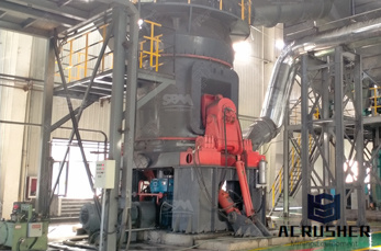
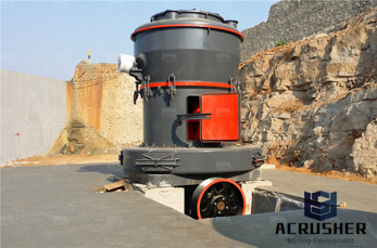
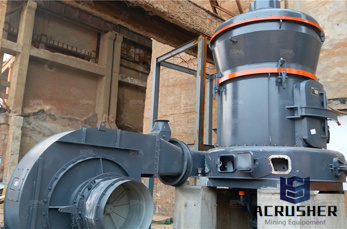
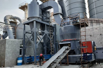
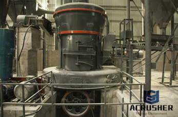
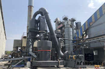
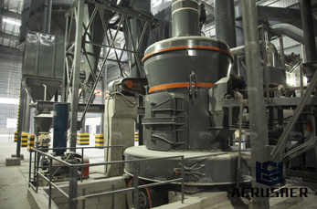
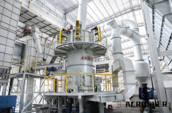
Crossrail block diagram of portal / gantry milling ma- .. The pressure can be maintained in the circuit. Get Price; Hydraulic system vertical roller mill operation - SlideShare. Mar 25, 2015 . The hydraulic system of vertical mill is an important system, the main function of the hydraulic system is to break the grinding roller, which is. Get Price
Hydraulic Schematic Diagrams Of Mill Plant. impact crusher parts diagram. schematic diagram of crusher plant - Rock Crusher Equipment schematic diagram of crusher plant XSM is a leading global manufacturer of crushing and milling equipment (schematic diagram of crusher plant),XSM also supply . Service And Support .
Most of our customers are choosing the correct spool type as they expected, but for few clients, it is better to know more than about hydraulic spool valve diagram before purchasing hydraulic directional valves. – finotek
components of single line diagram of cement plant pdf. THIS PAGE INTENTIONALLY LEFT BLANK, This reference . Electrical substation - Wikipedia- components of single line diagram of cement plant pdf,smaller generating plants were converted to, of transmission lines or other components to and, layout is the preparation of a one-line diagram, .Concrete Batch Plant Operator Study Guide ...
Aug 25, 2016· Hydraulic accumulator A raised weight accumulator consists of a vertical cylinder containing fluid connected to the Hydraulic Schematic Diagrams Of Mill Plant, Protable Plant .
TS 112 - Process and Instrumentation Diagrams (P&ID) SA Water - Technical Standard Revision 2.0 - 16 December 2015 Page 3 of 27 For Official Use Only Uncontrolled When Printed Or Downloaded
Hydraulic Schematics Accurate diagrams of hydraulic circuits are essential to the technician who must repair it. If you don't understand how the system operates, it is very difficult to diagnose possible hydraulic problems. This looks very complicated. To make it easier to understand, we are going to learn how to look at individual
WhatsApp)