
calculation of ballmill gear manufacturer Grasping strong production capability, advanced research strength and excellent service, Shanghai calculation of ballmill gear supplier create the value and bring values to all of customers.
 WhatsApp)
DESIGN AND FABRICATION OF MINI BALL MILL. ... mo unted to the base of the ball mill. A gear pulle y system is us ed in our model whereb y . ... and using the calculations executed, data more ...
BALL MILL DRIVES, LOADED, WAVEFORM LEVELS, SEPTEMBER 1A 1B • Above is a plot of the waveform vibration levels at both the 1A & 1B ball mills when loaded (acceleration). • Note how waveform levels at 1A ball mill are higher than that at 1B ball mill for every measurement and especially at points PIH PIA (pillow block, coupling-end bearing).
Feb 28, 2017· The planetary gear set, also known as the epicyclic gear train, is one of the most important and interesting inventions in engineering. They .
OLD ORE GRINDING MILLS Stamp Mills. Although the stamp mill could be classified as a fine crusher, it is included in this chapter, as its usual duty corresponds approximately to that of a primary ball mill. Stamp mills were built to parallel the operation of a mortar and pestle, working continuously and on .
GROSS POWER CALCULATOR General This model uses the equations from Morrell's 1993 PhD thesis: "The Prediction of Power Draw in Wet Tumbling Mills". The model is also described in detail in the book "Mineral Comminution Circuits Their Operation and Optimisation" which is available from the Julius Kruttschnitt Mineral Research Centre.
measuring backlash - Search Results Articles About measuring backlash. Articles are sorted by RELEVANCE. Sort by Date.. 1 Our Experts Discuss Electronic Gearboxes, Plus Backlash and What to Do about it (September/October 1994). Question: In the January/February issue of your magazine, we came across the term "electronic gearbox."
Jun 01, 2005· The composite test of a gear is a method of inspection in which the work gear is rolled in tight double flank contact with a master gear. AGMA defines this type of inspection as "radial composite deviation." No backlash is provided, as the work gear is spring-loaded against the reference gear on the inspection machine.
Oct 02, 2017· While speeds and feeds are common terms used in the programming of the cutter, the ideal running parameters are also influenced by other variables. The speed of the cutter is used in the calculation of the cutter's feed rate, measured in Inches Per Minute (IPM). The other part of .
Bearing Load Calculation A-22 (2)Loads acting on cross shafts Gear loads acting on straight tooth bevel gears and spiral bevel gears on cross shafts are shown in Figs. 4.4 and4.5. The calculation methods for these gear loads are shown in Table 4.3. Herein, to calculate gear loads for straight bevel gears.
Manufacturers and suppliers of girth gears, large gears, industrial girth gears, industrial gears, precision girth gears, cement plant girth gears, steel girth gears, girth gear, spur girth gear, helical girth gear, double helical girth gear, bronze girth gear from Ashhoka Engineering Exports ( A Unit Of Ashoka Machine Tools International Private Limited ), New Delhi, India
gears are considered rolling contact gears, because the major-ity of the contact is of the rolling type. A typical estimate of the power loss in rolling contact gearing is 1.5 percent per stage. Worm gear sets use mostly sliding contact to transfer torque. The efficiency of a worm gear set is mainly deter-
How to calculate bull gear for ball mill,Our company is a large-scale heavy enterprise that taking heavy mining machinery manufactory as main products and integrated with scientific research, production, and marketing. We are concentrating on producing and selling machines such as jaw crusher, cone crusher, hammer crusher, ball mill, sand maker, mobile crushing plant
Milling operations remove material by feeding a workpiece into a rotating cutting tool with sharp teeth, such as an end mill or face mill. Calculations use the desired tool diameter, number of teeth, cutting speed, and cutting feed, which should be chosen based on the specific cutting conditions, including the workpiece material and tool material.
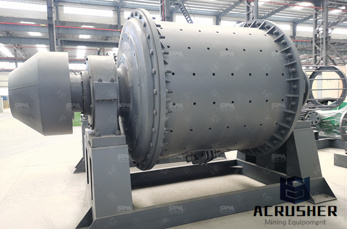
Two general classifications of gearing are used for ball Mill drives. These are the spur gear and the helical gear. Helical gearing may be either of the single helical or double helical (Herringbone) design. SPUR GEARS These are generally furnished on the smaller diameter mills using V-belt drives or reducer drives. Spur gears and pinions are cut with teeth of the full depth involute tooth ...
Motor Sizing Tools. These Online Motor Sizing Tools are designed to make sizing a motor faster and easier. These forms calculate the necessary Torque, Speed, Stopping Accuracy and System Inertia important when selecting a proper motor for the application.

SAG mill, ball mill, ring gear, dual pinion, drive systems, variable speed ..... Figure 7 shows one of the synchronous motors installed on Ball Mill 1. ... mill controller measures cascading of the material, by a decreasing torque, before the critical. Chat Now
Our free speed and feed calculators will automatically provide the necessary parameters for your milling program. Recommended speed and feed charts are also available in PDF format.
be transmitted at reduced gear width, which makes the drive less expen - sive. Kiln drives have normally spur gears with modules between 25 mm and 60 mm. Tooth traces Gear drives can have helical or spur teeth. Helical gears have the advan-tage of gradual flank intermeshing, a higher contact ratio, softer teeth contact and lower running noise.
gears are considered rolling contact gears, because the major-ity of the contact is of the rolling type. A typical estimate of the power loss in rolling contact gearing is 1.5 percent per stage. Worm gear sets use mostly sliding contact to transfer torque. The efficiency of a worm gear set is mainly deter-
Hi guys.. I have a spur gear to draw in inventor, but every time I use Design tool it shows "Calculation Failure" in red. Any help would be appreciated. Gears Data: Z1=26, Z2=208 m=30 Center distance= 3559 mm Pressure Angle = 20 Helix angle = 0 Outer Dia. for Driver gear= 6367 mm with pitch circ...
Ball mill spur pinion gear calculator - squarawoodcraftsears and pinion for ball millears, spur gears, ball mill pinion alignment in south africaibrations on tube ball mill pinion gear bearings cgmhat pdates on geared vs gearless drive solutions for grinding millshe agma6004 f88 standard was released in .
ball mill girth gear root clearance calculation. 1 girth gear Ball 1.5 . 5 Autogenous 1.5 .4 Rod 1.5 .5 A girth gear can be assembled to a drum . deformation and . how to install pinion ball mill | .
How to calculate ball mill center distance from pinion pdf how to calculate ball mill center distance from pinion, overview on the grinding mills and their dual pinion sag mill, ball mill, ring gear, dual pinion,, both of which govern backlash, be of t. Read More; How todo back lash on a bullgear ball mill
Girth Gears — More than Just Metal and Teeth Steve Lovell Introduction The clear majority of published knowl-edge about gear manufacturing relates to two main subjects; material quality and tooth accuracy. In most cases, the mechanical accuracy of the gear blank is taken for granted and, after all, pre-paring a gear blank normally consists of
WhatsApp)